This article mainly introduces the reasons why grounding is important and the corresponding grounding methods for electromagnetic flowmeters.
Why is Grounding of Electromagnetic Flowmeters Particularly Important? How to Ground Them?
The signal of an electromagnetic flowmeter is relatively weak, with only 2.5–8 mV at full scale and just a few microvolts at low flow rates. Even slight external interference can affect the accuracy of the instrument. Therefore, the grounding of electromagnetic flowmeters is particularly crucial.
The following points should be noted when grounding an electromagnetic flowmeter:
- The measuring tube, shell, shielded wire of the sensor, as well as the converter and secondary instrument, all need to be grounded.
- The sensor and converter shall be grounded separately, and must not be connected to motors or process pipelines. The grounding resistance should be less than 10 Ω.
- The sensor and converter shall be grounded on-site, while the shield layer connected to the secondary instrument shall be grounded on the control room side. Never ground at multiple terminals, otherwise interference may be introduced due to different potentials.
- If the sensor is installed on a metal pipe without an insulating coating inside the pipe, it can be grounded at the grounding terminal of the sensor. If the sensor is installed on a plastic pipe or a pipe with an insulating coating or lining, grounding rings (or short pipes with grounding electrodes) shall be installed at both ends of the sensor. This ensures that the medium flowing in the pipe is short-circuited to the ground and has zero potential.
What Are the Methods for Generating Magnetic Fields in Electromagnetic Flowmeters? What Are Their Advantages and Disadvantages?
The working principle of an electromagnetic flowmeter is that the flowing fluid cuts magnetic lines of force to induce an electromotive force, and then the fluid flow rate is measured by measuring the electromotive force. Therefore, the magnetic field that generates magnetic lines of force is very important. The magnetic field strength should not only be strong, but also constant and uniform. There are usually three excitation methods to generate magnetic fields.
DC Excitation
DC excitation uses direct current to excite the magnetic field or permanent magnets to generate a constant magnetic field. It has the characteristics of being less affected by AC electromagnetic field interference, and the influence of self-induction in the liquid can be ignored. However, DC excitation tends to polarize the dielectric inside the pipe, resulting in the positive electrode being surrounded by negative ions and the negative electrode by positive ions. This increases the internal resistance between the electrodes and destroys the original measurement conditions. Meanwhile, for pipes with large diameters, permanent magnets are large in size, which is neither economical nor very bulky.
AC Excitation
AC excitation uses 50 Hz power frequency alternating current for excitation. This excitation method can eliminate the polarization effect on the electrode surface, reduce the internal resistance of the sensor, and the output AC signal is easy to convert and amplify. However, the alternating magnetic flux will generate interference electromotive force, which has the same frequency as the signal electromotive force and a phase difference of 90°. Therefore, it is called quadrature interference or 90° interference. In severe cases, the interference electromotive force exceeds the signal electromotive force, making the instrument unable to work.
Constant Current Square Wave Excitation
Constant current square wave excitation uses positive and negative alternating rectangular wave constant current generated in the signal converter as the excitation current. This current is input into the excitation coil to generate an alternating magnetic field, and its frequency is only 1/2 to 1/8 of the power frequency. This circuit not only overcomes the polarization effect easily generated at the electrodes in DC excitation mode, but also overcomes the interference voltage formed by the electrode-conductive fluid-electrode in AC excitation. At the same time, the circuit is equipped with an excitation current adjustment loop, so the fixed coefficient of the sensor can be marked to facilitate the interchange between sensors. This circuit has no interference compensation mechanism and no compensation mechanism for power supply voltage and frequency fluctuations, so it is an ideal excitation method.
What Are the Requirements for Installing Electromagnetic Flowmeters?
The sensor can be installed vertically, horizontally or obliquely, but the full-pipe condition shall be ensured. That is, it should be installed where the measuring tube can be filled with liquid at all times to prevent interference from pointing to full scale when there is no liquid in the measuring tube. Vertical installation is preferred, allowing the liquid to flow through the instrument from bottom to top. If vertical installation is not possible, horizontal installation is also acceptable, as shown in the figure.
- When the measured medium contains a large amount of solid particles, vertical installation should be adopted to avoid wear on the lining (horizontal installation will cause local wear).
- The signal of the electromagnetic flowmeter is weak, with only 2.5–8 mV at full scale and just a few microvolts at low flow rates. Even slight external interference will affect the measurement accuracy. Therefore, the sensor shell, shielded wire, measuring tube and the pipes at both ends of the sensor must be grounded, and a separate grounding point shall be set. They must not be connected to the common ground wire of motors and electrical appliances or water supply and drainage pipes. The converter part is already grounded through the cable, so do not ground it again to avoid introducing interference due to different ground potentials.
- The sensor installation location should be far away from all electromagnetic interference sources (such as high-power motors, transformers, etc.).
- The signal cable shall be the shielded cable specified in the manual, and no other cables shall be used instead. The signal lines and excitation lines shall be threaded through steel pipes for protection separately, and parallel arrangement of them shall be avoided, especially keeping away from power cables. The exposed parts of the connectors at both ends of the signal cable shall be kept as short as possible, and the shield layer shall be stripped only enough to connect to the terminals. The signal line should be as short as possible, and the converter should be placed as close to the sensor as possible.
- The sensor and converter must use the same phase power supply. Otherwise, due to the 120° phase difference between the detection signal and the feedback signal, the instrument cannot work normally.
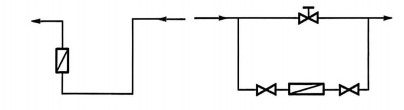
- There should be a straight pipe section of not less than 5D on the upstream side of the sensor. When there are valves or expanding pipes, the straight pipe section should be extended to 10D. The upstream stop valve should be fully open. If it cannot be fully opened, the valve should be set at a 45° angle to the electrode axis according to the throttling direction (i.e., insertion direction). The regulating valve should be installed on the downstream side. To prevent fluid disturbance, the cone angle of the expanding pipe should be less than 15°.
What Is an Electromagnetic Flowmeter? What Are Its Characteristics?
An electromagnetic flowmeter consists of two parts: a sensor and a converter, which are connected to each other by a special cable (including excitation lines and signal lines).
Advantages
- The measuring tube is a smooth straight tube without moving or flow-blocking components, resulting in almost no pressure loss. For large-diameter pipelines, the energy-saving effect is significant.
- The output of the flowmeter has a linear relationship with the flow rate, and the measurable pipe diameter ranges from 2.5 mm to 3 m.
- By reasonably selecting lining materials and electrode materials, it can measure the flow rate of various corrosive media.
- The installation requirements are low, with a front straight pipe section length of 5D and a rear straight pipe section of 3D (orifice plate: 20D and 7D; turbine flowmeter: 20D and 5D).
- The measurement accuracy is high, currently up to ±0.2% to ±0.5%.
- The range ratio is wide, up to 1:20.
Limitations and Disadvantages
- The medium temperature cannot be too high, generally not exceeding 180°C, and the pressure generally does not exceed 4.0 MPa.
- The measured medium must be a conductive liquid with a minimum conductivity > 5 μS/cm. The measured medium cannot contain a large amount of ferromagnetic substances and bubbles, and it cannot be used for non-conductive fluids such as gas, steam and petroleum products.
What Is the Commissioning Procedure for Electromagnetic Flowmeters?
- Open the valve to fill the system with liquid.
- Eliminate leakage points. If leakage occurs on one side of the flange, loosen the bolts on the opposite flange half a turn each time, and tighten the bolts on the leaking side accordingly. If this method does not work, remove the sensor to inspect the lining. If the lining is damaged, it can be treated by sanding.
- Remove residual gas in the system.
- Connect the power supply of the sensor and converter, and power on for preheating.
- Close the valve to fill the sensor with static liquid.
- Check and adjust the zero point of the converter.
- Reopen the valve to reach 100% flow rate, and check whether the output is correct and stable.


