This article mainly introduces measuring principle, futures, key advantages, technnical specificaions and installation requirements of radar level gauge.
Product Overview
1.1Measurement principle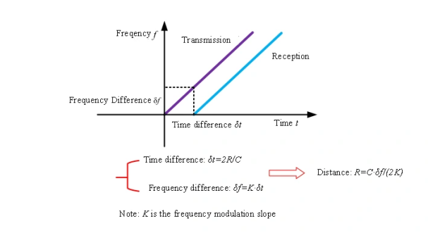
The principle of frequency modulated continuous wave radar level gauge is that the radar emits electromagnetic waves at the top of the tank. Electromagnetic waves are received by radar after being reflected by a medium. The frequency difference f between the received and transmitted signals is proportional to the distance R to the surface of the medium. R= C (speed)*f (Frequency difference) /2/K (Frequency modulation slope). Since the speed of light C and the frequency modulation slope K are known, by calculating the frequency differencef, the distance R from the radar installation location to the material surface can be obtained. Then, by subtracting the spatial distance from the radar to the material surface (referred to as the empty height) from the known total height of the tank, the height of the material level is obtained.
1.2 Features
1.Millimeter - wave radar, with a maximum measurement accuracy of ±2mm and a minimum measurement blind zone of 0.05m.
2.Smaller antenna size meets the measurement requirements of more working condition scenarios.
3.Various lens antennas, smaller emission angles, more concentrated energy, and stronger echo signals. Under the same working and mining conditions, it has higher reliability compared to other radar products.
5.It has stronger penetration and can be used normally even in the case of adhesion and condensation.
6.The dynamic signal range is larger, and the measurement of low dielectric constant media is more stable.
7.Multiple measurement modes, and the radar responds in the fast measurement mode.
1.3 Key Advantages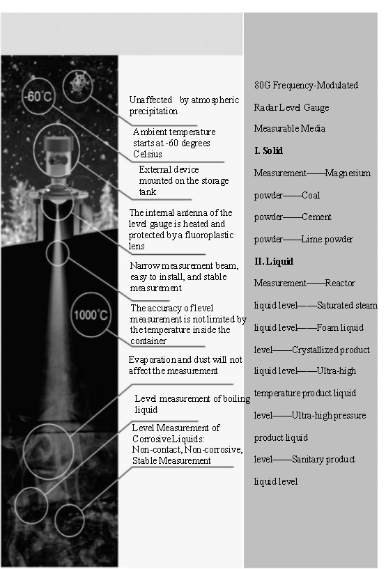
1.4 Technical Specifications
2 Installation Requirements
2.1 Location Selection
Figure1
The recommended distance A (the gap between the tank wall and the outer wall of the mounting nozzle) is approximately 1/6 of the tank diameter. However, the distance between the installed device and the tank wall should always be greater than 20 cm (7.87 in).
If the tank wall is not smooth (e.g., corrugated steel, welds, joints), it is recommended to install the device as far away from the tank wall as possible. If necessary, an antenna angle adjustment device can be used for installation to avoid interference reflection from the tank wall.
Installing the device in the center of the tank (2) is not recommended, as interference will cause signal loss.
Installing the device above the feed inlet (3) is prohibited.
2.2 Installation Method
Installation Method 1: Threaded Installation
Figure 2
Installation Method 2: Flange Installation
When using flange installation, the minimum distance between the instrument and the tank wall should be 200mm.
① Datum Plane② Center or Axis of the Vessel
Figure 3
Installation Method 3: Hoisting (Select based on specific installation conditions)
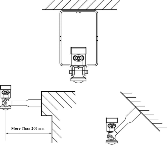 Figure 4


 Figure 4

