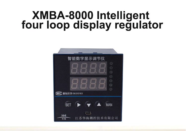
Product overview
The XMBA-8000 series intelligent four-loop display regulator produced by our company is the display mode of the input signals of the first four channels of the xmb-6000 series intelligent circuit display adjuster. It is developed by our company, appoint drag Japan integrated circuit manufacturers custom application-specific integrated circuit production, it not only collected all kinds of monitoring instrument in the automatic control system for most of the functions, but also integrates the CPU, I/D interface RS485 and RS232 communication interface, EPROM and D/A conversion circuit, supplemented by eclecticism, elaborate, repeated debug system, using the instrument has the following features:
1. The instrument hardware is greatly reduced, the system structure is relatively simple, and the process is significantly improved. There are no flying wires and potentiometers.
2. Four types and five alarm outputs can be set, with more than a dozen alarm methods. Four relays can be arbitrarily assigned to one - to four-channel input measurement control; Four-way input can realize unified upper and lower alarm; It can be set as one of the switch quantities to monitor the other three switch quantities selectively to realize the intelligent sound-light alarm function with sound attenuation time.
3. Optional add 1, 2 or 3 D/A analog outlet, which can realize real-time analog output of the instrument, analog output of the minimum value of the instrument, analog output of the maximum value of the instrument, and analog output of the average value of the instrument. It is also possible to set any 1-way continuous 3-way analog output as the starting point.
4. The input of linear signal can define the zero value, full value and decimal number of each line, and can also show the function of adding small signal to the square root.
Product selection
| XMBA |
—— |
Instruction
|
|
Design No.
|
8 |
8000 series instruments
|
|
Display
|
1 |
Four screens display
|
| 2 |
Single screen + four - streamer
|
|
Input (Same signals)
|
1 |
Thermocouple (E、K、S、B、J、T、R、N)
|
| 2 |
RTD (Pt100、Cu50、Cu100、BA1、BA2、G)
|
| 3 |
Voltage DC(0~10mA、4~20mA)
|
| 4 |
|
| 5 |
With output pressure resistance value and linear resistance value (0~400Ω)
|
|
Control output and adjustment mode
|
1 |
Only display 4 channels measuring value , no control
|
| 2 |
Four channels uniformly set upper and lower limit alarm values (public 2 relays)
|
| 3 |
Four independent upper and lower limit alarm values (public 2 relays)
|
| 4 |
Four independent sets of upper or lower limit alarm value (one relay for each)
|
| 5 |
The first and second channels independently set the upper and lower limit alarm values (each only USES 2 relays)
|
| 6 |
There are 3 alarm outputs in the first channel and 1 alarm output in the second channel
|
| 7 |
The first channel has 4 alarm outputs
|
| 8 |
SP3 is used to monitor other alarm points and has an acousto-optic alarm function
|
|
Dimension
|
H |
Horizontal 160×80
|
Portiforium 152×76
|
| V |
Vertical 80×160
|
Portiforium 76×152
|
|
Transmitter output
|
A |
A |
A |
No output
|
| B |
B |
B |
output 0~10mA
|
| C |
C |
C |
output 4~20mA
|
| D |
D |
D |
output 0~5V
|
| E |
E |
E |
output 1~5V
|
| F |
F |
F |
|
|
Timing function
|
S |
Without timing function
|
|
With timing function
|
|
Output power 24V
|
P |
Without 24VDC output as default
|
| |
With 24VDC output(2 Wires transmitter power option)
|
|
Communication
|
T |
No communication
|
|
With RS485 or RS232 communication
|
|
Power supply
|
|
220VAC
|
| K |
Switch power supply 85~260VAC
|
| W |
Switch power supply 18~36VDC or 18~36VAC
|
|
| |
Technical indicators
1. Measurement accuracy: ±0.5%FS+1 word
2. Adjustment control accuracy: bit: ±0.5%FS
3. Output accuracy of analog converter: ±0.5%FS, ±0.2%FS
4. Simulated input impedance:
Current signal: 50 or less Ω; A voltage signal: 500 k or Ω;
Thermal resistance exterior resistance: 10 or more Ω; Thermocouple signal: 100 k Ω or higher
5. Analog output impedance:
Current signal: 0 ~ 10 ma acuity 1.5 K Ω; 4 ~ 20 ma Ω 150 or higher
Voltage signal: 0 ~ 5 v, 1 ~ 5 v output impedance Ω 1 or less
6. Alarm mode: upper limit, lower limit, upper limit, lower limit, upper loop error, lower loop error, double loop error, OK mode, absolute value mode, etc. 7. Relay contact capacity: AC22V 3A (resistive load)
8. After the relay, set parameters to maintain time: ≥20 years
9. Power supply: AC220V, 50Hz, ≤6W or 24V
10. Working environment requirements: temperature: 0~50℃, relative temperature: ≤85% no corrosive substance, no vibration.
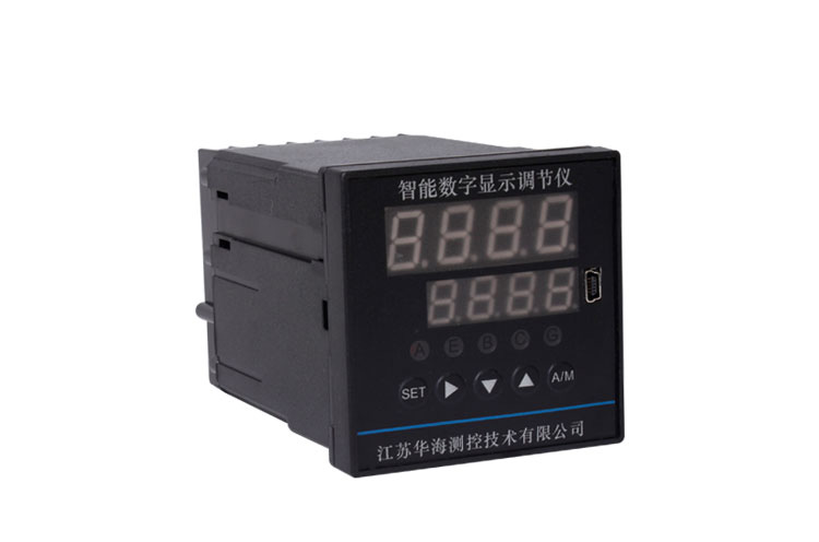
Display description
1. Four-screen display: the PV1 screen displays the measured value of the first input signal
The PV2 screen displays the measurement of the first input signal
The PV3 screen shows the measurements of the first input signal
The PV4 screen shows the measurements of the first input signal
Note: if the meter is 16 road patrol:
Measurement values of 1~4 channels are displayed at the same time, indicating lights H, D and F are not on
Measurement values of 5~8 channels are displayed at the same time. Indicator light F is on, while indicator light H and indicator light D are not
The measurement values of 9~12 channels are displayed at the same time. The indicator lights D are on, H and F are not
Measurement values of 13~16 channels are displayed at the same time, indicating lights D and F are on, but H is not
2. Single screen + four-light column: single screen: the display screen can display the measurement value of the input signal arbitrarily, press the ▲ key to switch.
Light column 1: display all the input measurement signals in the form of percentage;
Light column 2: display the second input measurement signal as a percentage;
Light column 3: display the third input measurement signal in percentage form;
Light column 4: display the measurement signal of the fourth input in the form of percentage;
Note: if the instrument is for 16-channel inspection, the display screen displays the measured value of 1-16-channel input signal.
The percentage of the measured value of 1~4 channels is displayed by four light columns at the same time, indicating lights G and H are not on;
The percentage of the measured value in 5~8 channels is displayed in four light columns at the same time. The indicator light H is on, while the indicator light G is not.
The percentage of the measured value in 5~12 channels is displayed in four light columns at the same time. The indicator light G is on, while the indicator light H is not.
The percentages of the measured values of 13~16 channels were displayed on four light columns at the same time, indicating lights G and H were on.
3. The indicator light
A light or J1 light: SP1 bit control indicator light.
E light or J2 light: SP2 control indicator light.
B dozen or J3 light: SP3 control indicator light.
C light or J4 light: SP4 control indicator light.
G lamp, H lamp, D lamp and F lamp are used to indicate the digital display channel.
Instrument use and maintenance
1. The instrument should be placed in a dry, ventilated place without corrosive gas, and the ambient temperature and relative humidity should meet the technical conditions.
2. Please choose the correct instrument model and relevant procedures according to your needs, so that users can avoid debugging or use them directly.
3. Due to the multiple functions of the instrument, the menu operating procedures and the correct wiring should be set according to the working conditions. If necessary, it is suggested that the user should send staff to the manufacturer to learn.
4. If the instrument is damaged due to the quality problem of the manufacturer, it shall be repaired by the manufacturer free of charge within one year.