Working principle
Industrial thermal resistance can be divided into platinum thermal resistance and copper thermal resistance.
Thermal resistance is the measurement of temperature by means of the characteristic that the resistance of a substance changes with the change of temperature. Thermal resistance heating part (temperature sensing element) is uniformly twisted on the framework made of insulating material by fine metal. When there is a temperature gradient in the measured medium, the measured temperature is the average temperature in the dielectric layer within the range of the temperature sensor.
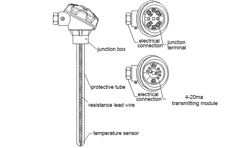
The assembly thermal resistance is mainly composed of junction box, protective tube, junction terminal, insulation sleeve box temperature sensing elements, and is equipped with various installation fixtures.
WZP type platinum resistance temperature sensor is a platinum wire winding. Double platinum resistance is mainly used in situations where two sets of display, record or regulator are needed to simultaneously detect the temperature at the same place. WZC copper resistance temperature sensor is a copper wire winding.
Platinum resistance
Platinum is the most ideal material for making thermal resistance. Its physical and chemical properties are stable, especially its anti-oxidation ability is strong, resistivity is high, and processing is good. The platinum resistance thermometer is one of the four standard instruments of ITS-90 international thermometer. It can transmit the standard temperature of 13.8033K~961.78 ~C. Industrial platinum resistance thermometers mainly have two kinds of indexing marks: Pt100 and Pt10. Pt1000, Pt800 and Pt500 are seldom used.
Copper resistance
Copper is also the most ideal material for making thermal resistance. It has low cost, easy to purify, high resistance temperature coefficient, good repetition test and easy to be processed into insulating copper wire. The resistance temperature characteristics of copper resistance in the range of - 50 ~ 150 C are almost linear. Copper resistance thermometers for industrial use have two kinds of indexing marks, Cu50 and Cu100. Because of the decreasing cost of platinum resistance, copper resistance has been replaced by platinum resistance in most cases.
Main Technical Indicators
The ratio of resistance value (R100) of thermistor inductance temperature element to resistance R0 of thermistor inductance temperature element at 0 ((R100/R0)
Grading number Pt100:A grade R0=100+0.06_B grade R0=100+0.12_R100/R0=1.3850
Temperature Measurement Accuracy of Thermal Resistance
The measurement accuracy is also called allowable deviation or allowable deviation. It refers to the degree of conformity between the resistance temperature characteristics of a specific branch of thermal resistance and the standard scale of this kind of thermal resistance. With Thermal Resistance I
Sample, theoretically speaking, there are no two thermal resistance with identical material, structure and processing state, so any thermal resistor is deviated from the standard scale, and the two test results of any thermal resistor are not consistent, and can only meet the standard scale to a certain extent. According to the degree of conformity or deviation, the bar thermal resistance can be divided into A and B levels. Details can be found in the following table:
|
Performance Type
|
A grade accuracy
|
B grade accuracy
|
|
Temperature tolerance(℃)
|
Platinum resistance
|
±(0.15+0.2%|t|) |
±(0.30+0.5%|t|) |
|
Basic error
|
Nominal resistance R0(Ω)
|
Pt10 |
10±0.006 |
10±0.012 |
| Pt100 |
100±0.06 |
100±0.12 |
|
Resistance ratio(R100/R0)
|
Platinum resistance
|
1.3850±0.0010 |
|
Measure range(℃)
|
Platinum resistance
|
-200~650 |
-200~850 |
|
Note: Class A accuracy is not applicable to two-wire platinum resistance ; Class A accuracy is not applicable to Pt100 resistance above 650 C; and Pt10 is mainly used for platinum resistance whose working temperature extends beyond 600 C.
|
Stability of Thermal Resistance
|
|
Platinum resistance
|
| A |
B |
|
Limit temperature
|
When the upper and lower limits are 250 hours respectively, the change value of resistance measured at 0 C or converted to the change value of temperature
|
≤0.15℃ |
≤0.30℃ |
|
Temperature cycle
|
After 0-upper limit-room temperature-lower limit-temperature-0 C temperature cycle, the measured resistance change is converted into temperature change value Pt10.
|
|
Thermoelectric effect
|
The maximum potential measured by changing the insertion depth at 100 C
|
≤20μV |
|
Self heating effect
|
When the excitation current is changed from 0.03 to 10 mA at 0 C, the measured resistance increment is converted to the maximum value of temperature increment or the self-heating effect evaluation value.(Pt10:0.1~30mA)
|
≤0.30℃ |
Response time
When the temperature changes step by step, the output of the thermal resistance changes to 5% of the step change. The required time is called thermal response time, expressed in t 0.5.
Nominal pressure of thermal resistance
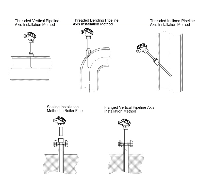
Generally speaking, the protection tube can withstand external pressure (static) without breaking at this working temperature. The allowable nominal pressure is not only related to the material, diameter and wall thickness of the protective tube, but also to its structure, installation method, insertion depth and the type of velocity box of the medium under test.
Minimum insertion depth of thermal resistance
Generally not less than 300 mm (except for special products)
Self heating effect
When the measured current in the thermal resistance is 5 mA, the measured resistance increment should be converted to a temperature value of not more than 0.30 C.
Insulation resistance
The experimental voltage of insulation resistance at room temperature can be chosen as any value of DC 10-100V. The ambient temperature is in the range of 15-35 C, and the relative humidity should be no more than 80%. The insulation resistance at room temperature should not be less than 100M.
Lead System with Thermal Resistance
The temperature measured by thermal resistance refers to the temperature induced by the thermal resistance element at the end of the measurement. The temperature determines the size of the resistance element, but the output resistance value of the measuring element includes the resistance of the lead, so the size and stability of the lead resistance and the processing method directly determine the measurement accuracy of the thermal resistance. It is known from the grading characteristics of thermal resistance that the average variation rate of platinum resistance per degree resistance is 0.385Ω/C, the average variation rate of copper resistance per degree resistance is 0.428Ω/C. Lead resistance should not make the thermal resistance exceed the allowable deviation of its temperature measurement. Two-wire lead resistance is not more than 0.1Ω, otherwise technical treatment is needed to deduct the lead. Resistance. Lead resistance includes two parts: the lead resistance of thermal resistance product (called internal lead resistance) and the lead resistance between thermal resistance product and display instrument (called external lead resistance). Leading methods can be divided into three types:
Two-wire system: Thermal resistance products only give two leads, measuring resistance includes lead resistance, general lead resistance < 0.1Ω. The measurement error of two-wire lead method is large. It is generally used in situations where the lead is not long and the measurement accuracy is not high. The two-wire system only refers to the use of two leads in the internal leads of thermal resistance products, and three leads in the external leads installed by users.
Three-wire system: Thermal resistance products give three leads. If the resistance of three leads is equal, the influence of lead resistance on measurement results can be eliminated. Both internal and external leads use three leads, which is the most widely used wiring mode in industrial production. As shown in the figure below, as long as the resistance of the three leads is equal (i.e. R1 = R2 = R3), the resistance R0 of the temperature measuring element is independent of the resistance of the lead and can be expressed as R0 = RAC - RAB.
 |
 |
|
RTD ( 3 wires )
|
RTD ( 4 wires )
|
Four-wire system: Thermal resistance products give four leads. This method can completely eliminate the influence of lead resistance on the measurement results. The measurement accuracy is high. Generally, it is only suitable for precision measurement, such as standard platinum resistance thermometer.
As shown in the figure above, regardless of whether the resistance of the four leads R 1, R 2, R 3 and R 4 are equal or not, the resistance R 0 of the temperature measuring element is independent of the resistance of the lead and can be expressed as R0= (RAD+RBC-RAB-RCD)/2.
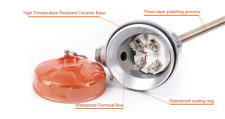
Thermal Resistance Structure
The assembled thermal resistance mainly consists of junction box, protective tube, junction terminal, resistance lead and temperature sensing resistance, and is equipped with various installation fixtures.
Product details
|
Type
|
Model code
|
Graduation |
Measure range℃
|
Protective tube material
|
Output
|
 |
|
Simplex platinum thermal resistance
|
WZP-620 |
PT100 |
-200-420 |
304
316L |
Direct output
|
| WZP-620 |
| WZPB-620 |
4~20mA output
|
| WZPB-620 |
|
Duplex platinum thermal resistance
|
WZP2-620 |
Direct output
|
| WZP2-620 |
| WZPB2-620 |
4~20mA output
|
| WZPB2-620 |
Installation diagram