Working principle
The working principle of sheathed thermocouple is that two ends of two different components of conductor are welded to form a circuit, and the direct measuring end is called the measuring end, and the terminal is called the reference end. When there is a temperature difference between the measuring end and the reference end, a thermal current will be generated in the circuit. When the display instrument is connected, the corresponding thermoelectric temperature value generated by the thermocouple will be indicated on the instrument.
The thermoelectric potential of the sheathed thermocouple will increase with the temperature of the measuring end. The thermoelectric potential is only related to the material of the armored thermocouple conductor and the temperature of both ends, and has nothing to do with the length and diameter of the thermoelectric pole.
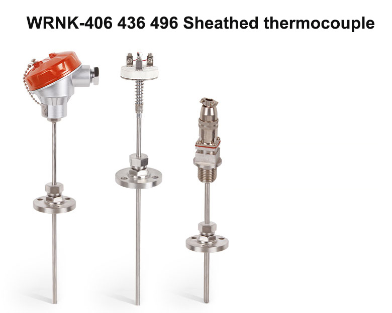
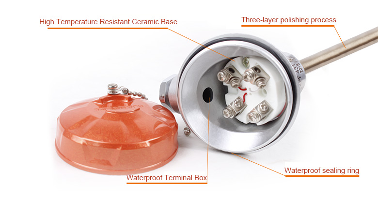
The structure of sheathed thermocouple is made of conductor, insulating oxidation mold and lcr18ni9ti stainless steel protective tube. Sheathed thermocouple products are mainly composed of junction box, terminal and sheathed thermocouple, and equipped with various fixed devices.
Product structure
The structure of the sheathed thermocouple is the same as that of the conventional assembled thermocouple except that the temperature measuring element, insulating material and protective sleeve in the five parts form the whole armor.
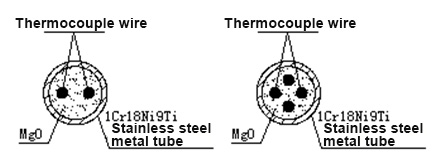
Sheath material (temperature measuring element, insulating material and protective sleeve): temperature measuring element means positive and negative two thermocouple wires for thermocouples. Magnesium oxide is used as insulating material between each thermocouple wire and between each thermocouple wire and the protective sleeve; metal tube is used to protect the insulating material and temperature measuring element. The sheath material technology makes the temperature measuring element, insulating material and protective sleeve become a non detachable and flexible compact entity. The sheath material is the base material for manufacturing sheathed thermocouples. The sheathed material cannot be directly used for measurement and construction. It can only be used as the base sheathed thermocouple after the measurement end and simple terminal are made.
Material structure
| ☆Material structure of sheathed thermocouple |
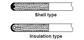
☆Measurement end (hot end) structure |
 |
 |
Technical indicators
Diameter and relevant parameters
|
Outer diameter of tube
|
8.0 |
6.0 |
5.0 |
4.0 |
3.0 |
|
Tube thickness
|
0.8~1.2 |
0.6~0.9 |
0.5~0.8 |
0.4~0.6 |
0.3~0.45 |
|
Thermocouple wire diameter
|
K、N、E、J、T |
1.2~1.4 |
0.9~1.0 |
0.7~0.9 |
0.55~0.6 |
0.45~0.6 |
| S、R、B |
0.45 |
0.45 |
0.45 |
0.4 |
0.3 |
Recommended operating temperature
|
Type
|
Graduation
|
Tube material
|
Outer diameter
|
Operation temperature
|
|
Long term service temperature
|
Short term service temperature
|
|
Sheathed Ni-Cr –Ni-Si
|
K |
1Cr18Ni9Ti |
φ3 φ4 |
600 |
700 |
| φ5 φ6 |
700 |
800 |
| φ8 |
800 |
850 |
| GH3030 |
φ3 |
800 |
900 |
| φ4 φ5 |
900 |
1000 |
| φ6 φ8 |
1000 |
1100 |
|
Sheathed Ni-Cr-Si –Ni-Si
|
N |
1Cr18Ni9Ti |
φ3 |
800 |
900 |
| φ4 φ5 φ6 |
900 |
1000 |
| φ8 |
1000 |
1100 |
| GH3030 |
φ3 |
900 |
1000 |
| φ4 φ5 |
1000 |
1100 |
| φ6 φ8 |
1100 |
1200 |
| GH3039 |
φ3 φ4 |
1000 |
1100 |
| φ5 φ6 φ8 |
1100 |
1200 |
|
Sheathed Ni-Cr –Cu-Ni
|
E |
1Cr18Ni9Ti |
φ3 |
350 |
450 |
| φ4 φ5 φ6 φ8 |
450 |
550 |
|
Sheathed Fe- Cu-Ni
|
J |
1Cr18Ni9Ti |
φ3 |
300/td> |
400 |
| φ4 φ5 φ6 φ8 |
400 |
500 |
|
Sheathed Cu-Cu-Ni
|
T |
1Cr18Ni9Ti |
φ3 φ4 φ5 |
200 |
250 |
| φ6 φ8 |
250 |
300 |
| φ5 φ6 φ8 |
1100 |
|
Model representation
|
Type
|
Model code
|
Graduation
|
Output
|
Wiring device
|
 |
|
Simplex Ni-Cr –Ni-Si
|
WRNK-406 |
K |
Directly output
|
Simple terminal board
|
|
Duplex Ni-Cr –Ni-Si
|
WRNK2-406 |
|
Simplex Ni-Cr –Ni-Si
|
WRNKB-406 |
4~20mA output
|
|
Duplex Ni-Cr –Ni-Si
|
WRNKB2-406 |
|
Simplex Ni-Cr –Ni-Si
|
WREK-406 |
E |
Directly output
|
|
Duplex Ni-Cr –Ni-Si
|
WREK2-406 |
|
Simplex Ni-Cr –Ni-Si
|
WREKB-406 |
4~20mA output |
|
Duplex Ni-Cr –Ni-Si
|
WREKB2-406 |
|
Simplex Ni-Cr –Ni-Si
|
WRCK-406 |
T |
Directly output |
|
Duplex Ni-Cr –Ni-Si
|
WRCK2-406 |
|
Simplex Ni-Cr –Ni-Si
|
WRCKB-406 |
4~20mA output |
|
Duplex Ni-Cr –Ni-Si
|
WRCKB2-406 |
|
Simplex Ni-Cr –Ni-Si
|
WRFK-406 |
J |
Directly output |
|
Duplex Ni-Cr –Ni-Si
|
WRFK2-406 |
|
Simplex Ni-Cr –Ni-Si
|
WRFKB-406 |
4~20mA output |
|
Duplex Ni-Cr –Ni-Si
|
WRFKB2-406 |
|
Simplex Ni-Cr –Ni-Si
|
WRMK-406 |
N |
Directly output |
|
Duplex Ni-Cr –Ni-Si
|
WRMK2-406 |
|
Simplex Ni-Cr –Ni-Si
|
WRMKB-406 |
4~20mA output |
|
Duplex Ni-Cr –Ni-Si
|
WRMKB2-406 |
|
Type
|
Model code
|
Graduation
|
Output
|
Wiring device
|
 |
|
Simplex Ni-Cr –Ni-Si
|
WRNK-496 |
K |
Directly output
|
With compensating wire
|
|
Duplex Ni-Cr –Ni-Si
|
WRNK2-496 |
|
Simplex Ni-Cr –Ni-Si
|
WREK-496 |
E |
|
Duplex Ni-Cr –Ni-Si
|
WREK2-491 |
|
Simplex Ni-Cr –Ni-Si
|
WRCK-496 |
T |
|
Duplex Ni-Cr –Ni-Si
|
WRCK2-496 |
|
Simplex Ni-Cr –Ni-Si
|
WRFK-496 |
J |
|
Duplex Ni-Cr –Ni-Si
|
WRFK2-496 |
|
Simplex Ni-Cr –Ni-Si
|
WRMK-496 |
N |
|
Duplex Ni-Cr –Ni-Si
|
WRMK2-496 |
|
Type
|
Model code
|
Graduation
|
Output
|
Wiring device
|
 |
|
Simplex Ni-Cr –Ni-Si
|
WRNK-436 |
K |
Directly output
|
Water proof type
|
|
Duplex Ni-Cr –Ni-Si
|
WRNK2-436 |
|
Simplex Ni-Cr –Ni-Si
|
WRNKB-436 |
4~20mA output
|
|
Duplex Ni-Cr –Ni-Si
|
WRNKB2-436 |
|
Simplex Ni-Cr –Ni-Si
|
WREK-436 |
E |
Directly output
|
|
Duplex Ni-Cr –Ni-Si
|
WREK2-436 |
|
Simplex Ni-Cr –Ni-Si
|
WREKB-436 |
4~20mA output
|
|
Duplex Ni-Cr –Ni-Si
|
WREKB2-436 |
|
Simplex Ni-Cr –Ni-Si
|
WRCK-436 |
T |
Directly output
|
|
Duplex Ni-Cr –Ni-Si
|
WRCK2-436 |
|
Simplex Ni-Cr –Ni-Si
|
WRCKB-436 |
4~20mA output
|
|
Duplex Ni-Cr –Ni-Si
|
WRCKB2-436 |
|
Simplex Ni-Cr –Ni-Si
|
WRFK-436 |
J |
Directly output
|
|
Duplex Ni-Cr –Ni-Si
|
WRFK2-436 |
|
Simplex Ni-Cr –Ni-Si
|
WRFKB-436 |
4~20mA output
|
|
Duplex Ni-Cr –Ni-Si
|
WRFKB2-436 |
|
Simplex Ni-Cr –Ni-Si
|
WRMK-436 |
N |
Directly output
|
|
Duplex Ni-Cr –Ni-Si
|
WRMK2-436 |
|
Simplex Ni-Cr –Ni-Si
|
WRMKB-436 |
4~20mA output
|
|
Duplex Ni-Cr –Ni-Si
|
WRMKB2-436 |
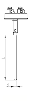
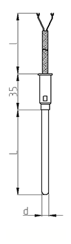
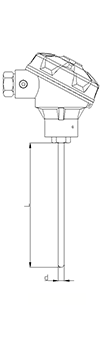
Installation diagram