 |
 |
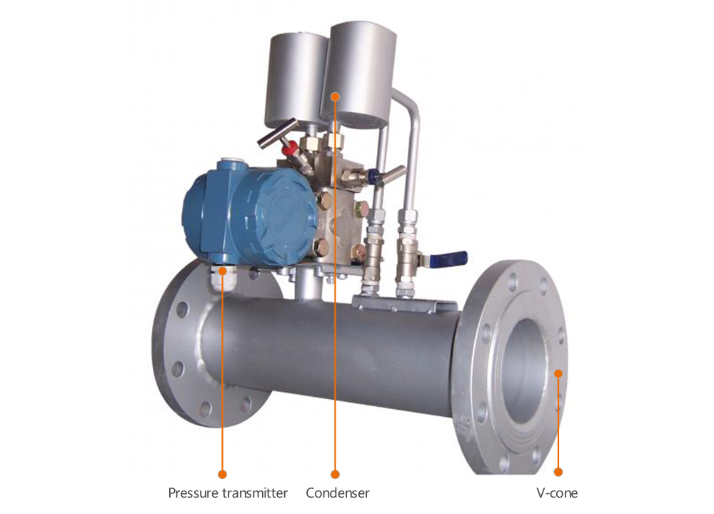
Product ·Structure diagram
Product Internal Structure|Decomposition Analysis|Just to give you a better understanding of the product
Committed to provide solution for field instruments
|
 |
Product • parameters
Various parameters for you to choose|HUAHAI instrument Strive for excellence
Committed to provide solution for field instruments
|
| Product name |
V-cone flowmeter |
Nominal diameter |
DN25 -DN1600 Caliber greater than DN1600 can also be made |
| Basic error |
±0.5%,±1.5%, ±2.5% |
Measured medium |
Liquid, gas (including natural gas), steam |
| Working pressure |
≦26.0 MPa |
Measured medium temperature |
<550℃ |
| Requirement for straight pipe section |
Upstream 0-3D,downstream 0-1D |
Power supply |
24V DC(Need to be equipped with differential pressure transmitter ) |
| Protective performance |
IP65 |
Explosion-proof performance |
Intrinsic safety type IbIICT5 |
| Display |
8 bit LCD display instantaneous flow and accumulative flow (Equip flow totalizer) |
Output signal |
4-20mA DC flow signal The output signal that conforms to the HART protocol |
|
 |
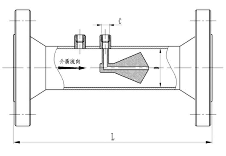 |
| Flange execution standard:JB/T81-1994、JB/T82.1-1994、JB/T82.2-1994 |
|
| Nominal diameter D |
L (mm) |
C |
Nominal diameter D |
L (mm) |
C |
| DN25 |
150 |
M12*1.5 |
DN350 |
900 |
M20*1.5 |
| DN32 |
165 |
M12*1.5 |
DN400 |
1050 |
M20*1.5 |
| DN40 |
200 |
M12*1.5 |
DN450 |
1150 |
M20*1.5 |
| DN50 |
250 |
M20*1.5 |
DN500 |
1260 |
M20*1.5 |
| DN65 |
275 |
M20*1.5 |
DN600 |
1380 |
M20*1.5 |
| DN80 |
300 |
M20*1.5 |
DN700 |
1500 |
M20*1.5 |
| DN100 |
350 |
M20*1.5 |
DN800 |
1600 |
M20*1.5 |
| DN125 |
400 |
M20*1.5 |
DN900 |
1750 |
M20*1.5 |
| DN150 |
450 |
M20*1.5 |
DN1000 |
1850 |
M20*1.5 |
| DN200 |
550 |
M20*1.5 |
DN1400 |
2000 |
M20*1.5 |
| DN250 |
650 |
M20*1.5 |
DN1600 |
2200 |
M20*1.5 |
| DN300 |
700 |
M20*1.5 |
DN1500 |
2500 |
M20*1.5 |
|
 |
| Model |
Description |
| HLVZ |
V-cone flowmeter |
| |
Code |
Classification by structure |
| |
01 |
Pipeline type |
| |
02 |
Embedded type |
| |
03 |
Insertion type |
| |
Code |
Caliber |
| |
25-3000 |
DN25-DN3000 |
| |
Code |
Pressure class(MPa) |
| |
1.6 |
1.6 |
| |
2.5 |
2.5 |
| |
4.0 |
4.0 |
| |
6.3 |
6.3 |
| |
10 |
10 |
| |
16 |
16 |
| |
26 |
26 |
| |
Code |
Medium |
| |
1 |
Liquid |
| |
2 |
Gas |
| |
3 |
Steam |
| |
Code |
Compensation form |
| |
N |
No pressure, temperature compensation |
| |
P |
With pressure compensation output |
| |
T |
With temperature compensation output |
| |
Code |
Transmitter differential pressure range |
| |
0 |
Micro differential pressure range |
| |
1 |
Low differential pressure range |
| |
2 |
Medium differential pressure range |
| |
3 |
High differential pressure range |
| |
Code |
Whether with the field display |
| |
W |
Throttling device sensor |
| |
X |
Intelligent throttling device (flowmeter) |
|