|
| Code |
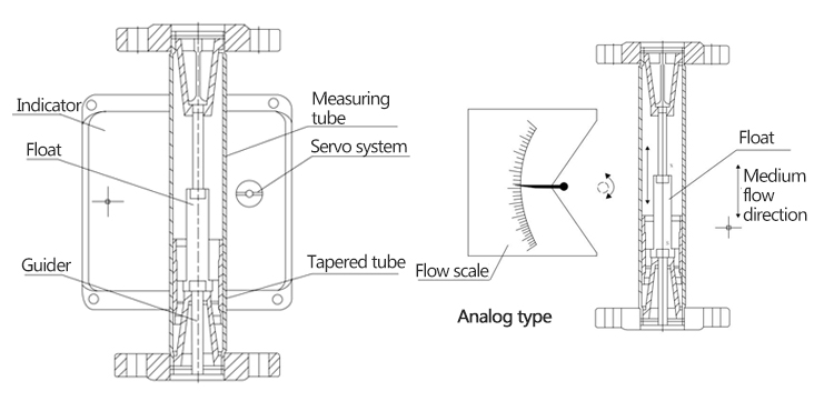
Measuring tube structure A |
HH-50
HH-51
HH-52
HH-53R
HH-53L |
Low in and Top out
Low in and top horizontally out
Low horizontally in and Top horizontally out
Right in and left out
Left in and right out |
| |
Code |
Connect-liquid material B |
R0
R1
RP
Ti
RL |
0Cr18Ni12Mo2Ti
1Cr18Ni8Ti
PTFE(F4 liner) (only HH-51,HH-52)
Ti alloy(only HH-51,HH-52,HH-53R,HH-53L)
316L |
| |
Code |
Pipe caliber C |
DN15
DN25
DN50
DN80
DN100
DN150
DN200 |
15
25
50
80
100
150
200 |
| |
Code |
Accessory mechanism D |
None
T
Z
G
Y |
Clamp type(only HH-51,HH-52,HH-53R,HH-53L)
Damping type
High temperature type
High pressure type |
| |
Code |
Indicator form code combination |
| E |
See the following sheet |
| HH-50 |
R0 |
DN50 |
G |
E |
|
|
 |
 |
 |
 |
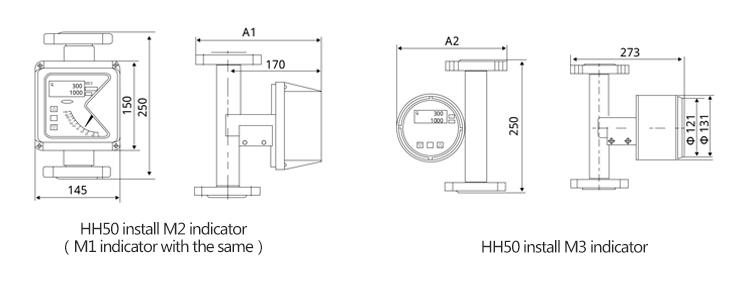
| 1、HH50 type |
| a、HH50 series standard type dimensions and weight pressure loss table |
|
 |
| Specification |
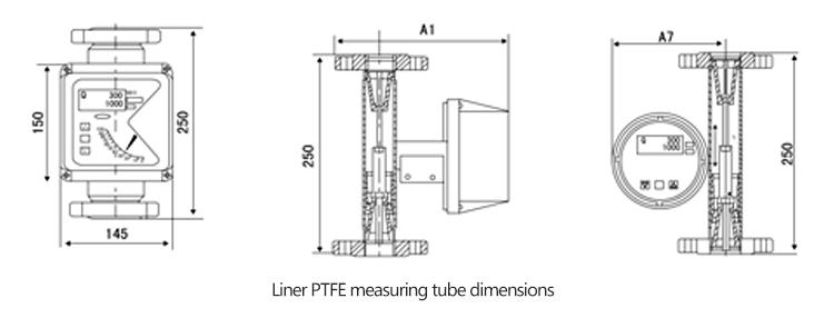
HH50 standard type dimensions and weight pressure loss table |
| Symbol |
A1 |
A2 |
G1 |
△P |
| DN15 |
220 |
241 |
6.0 |
14 |
| DN25 |
230 |
260 |
7.5 |
19 |
| DN50 |
255 |
300 |
11 |
23 |
| DN80 |
270 |
330 |
16.5 |
33 |
| DN100 |
280 |
350 |
17.5 |
42 |
| DN150 |
320 |
405 |
36 |
60 |
| DN200 |
350 |
460 |
51 |
70 |
|
| |
| b、HH50 series clamp type dimensions and weight table |
|
| Specification |
HH50/T dimensions and weight table |
| Symbol |
A3 |
A |
G2 |
| DN15 |
245 |
100 |
6.5 |
| DN25 |
265 |
110 |
10.5 |
| DN50 |
305 |
120 |
14 |
| DN80 |
335 |
140 |
20 |
| DN100 |
360 |
150 |
21 |
|
 |
|
Note:G2 is instrument weight (kg);
HH50 clamp type outline dimension |
|
| |
| C、HH50 series liner PTFE type dimensions and weight table |
|
 |
| Specification |
HH50/T dimensions and weight table |
| Symbol |
A1 |
A7 |
G3 |
| DN15 |
220 |
245 |
6 |
| DN25 |
230 |
265 |
7.5 |
| DN50 |
255 |
305 |
11 |
| DN80 |
270 |
335 |
26.5 |
| DN100 |
280 |
360 |
17.5 |
|
|
| Note:G3 is instrument weight (kg); |
|
| |
| 2、HH51 type dimensions and weight pressure loss table |
|
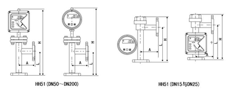 |
| Caliber |
H (mm) |
L (mm) |
A (mm) |
G4 |
△P |
| DN15 |
350 |
250 |
120 |
7 |
18 |
| DN25 |
350 |
250 |
120 |
8 |
22 |
| DN50 |
600 |
250 |
120 |
15 |
28 |
| DN80 |
700 |
250 |
150 |
25 |
35 |
| DN100 |
700 |
250 |
150 |
29 |
45 |
| DN150 |
760 |
300 |
180 |
53 |
58 |
| DN200 |
800 |
350 |
200 |
61 |
70 |
|
| Note:1、G4 is instrument weight (kg); 2、△P is pressure loss(kPa). |
|
| |
| 3、HH52 series dimensions and weight pressure loss table |
|
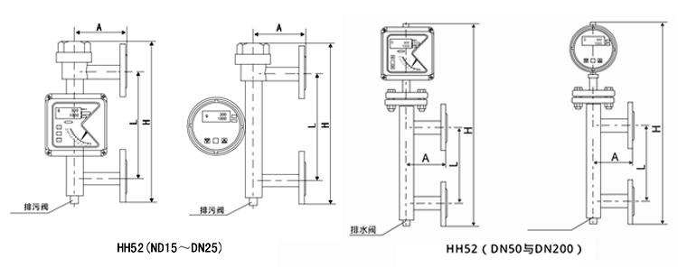 |
| Caliber |
H (mm) |
L (mm) |
A (mm) |
G5 |
△P |
| DN15 |
500 |
250 |
120 |
5 |
20 |
| DN25 |
500 |
250 |
120 |
8 |
28 |
| DN50 |
650 |
250 |
120 |
14 |
36 |
| DN80 |
800 |
300 |
150 |
31 |
45 |
| DN100 |
800 |
300 |
150 |
50 |
58 |
| DN150 |
850 |
350 |
180 |
67 |
63 |
| DN200 |
880 |
400 |
200 |
81 |
70 |
|
| Note:1、G5 instrument weight (kg); 2、△P is pressure loss(kPa). |
|
| |
| 4、HH53 series dimensions and weight pressure loss table |
|
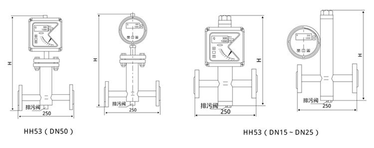 |
| HH53/R P dimensions and weight table |
|
| Caliber |
H(mm) |
G6(kg) |
△P |
| DN15 |
430 |
6.5 |
30 |
| DN25 |
450 |
10.5 |
35 |
| DN50 |
540 |
21 |
40 |
|
| Note:1、G6 is instrument weight (kg); 2、△P is pressure loss(kPa). |
|
 |
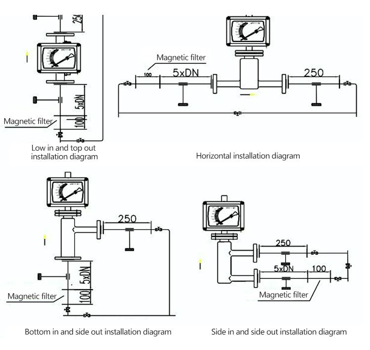
1. Before the installation operation, remove all packaging, remove the parts of the fixed float that are in the transport and check for damage.
2. Before installing to the process pipeline, clean the welding slag in the pipeline to prevent the impurities in the pipeline from clogging the instrument, affecting the normal use.
3. In order to ensure the measurement accuracy, it is recommended to install a 5DN inlet straight pipe part in the upstream of the flowmeter, and install 250mm outlet straight pipe part in the downstream.
4. The flowmeter has vertical installation and horizontal installation form, if it is vertical installation form, installation verticality should be guaranteed better than 1%, if it is horizontal installation form, installation verticality and levelness should be guaranteed better than 1%.
5. If the medium contains solid impurities, the filter should be installed between the valve and the straight pipe part; If the medium contains ferromagnetic material, the magnetic filter should be installed upstream of the flowmeter.
6. Because the metal tube rotameter is installed with a magnetic remote transmission system, it is necessary to ensure that the magnetic field generated by other equipment around not affect the measurement results.
7. The instrument installed in the pipeline should not be affected by the pressure, and the exit and entrance of the instrument should be supported by suitable pipeline, so that the instrument is in the minimum stress state.
8. When measuring low temperature medium, it is necessary to choose the clamp type. |
|
 |