Focvor Series Smart Vortex Flowmeter
Huahai M&C for Thirteen Years|Profession Famous Brand |2017 Overall Upgrade|New Products Solemn On-Line
Vortex flowmeter decomposition diagram
Persistence is the key to success |Manufacture Huahai High Quality Products
Bring New Products to Market in 2017
Product • Structure Detail Drawing
Product Internal Structure|Decomposition Analysis|Just to give you a better understanding of the product
Committed to provide solution for field instruments
Product • performance index
Various parameters for you to choose|HUAHAI instruments strive for excellence
Committed to provide solution for field instruments
 |
| Measuring Medium |
Gas, liquid, steam |
| Perform Standard |
Vortex flow sensor(JB/T 9249-1999) |
| Verification Regulation |
Vortex Flowmeter(JJG 1029-2007) |
| Connection Mode |
Wafer type、Flange type |
| Nominal Diameter |
DN25、DN32、DN40、DN50、DN65、DN80、DN100、DN125、DN150、DN200、DN250、DN300 |
| Flange Standard |
Conventional standard |
GB/T9113-2000 |
| Other standards |
International pipe flange standard |
Such as the German standard DIN,、American Standard ANSI、Japanese standard JIS |
| Domestic pipe flange standard |
Such as the standard of the ministry of chemical industry、the standard of the ministry of machinery |
| Verification Conditions |
Verification device |
Sonic nozzle flow verification device |
| Accuracy Class |
class 1.5 |
| Range Ratio |
1:10 |
| Flow Velocity Range |
Liquid:0.5~7m/s Gas:5~50m/s |
| Instrument Material |
304 Stainless steel,316 Stainless steel |
| Temperature Range |
-25℃~100℃、-25℃~+280℃、-25℃~+320℃ |
| Pressure Class |
1.6MPa、2.5MPa、4.0MPa |
| Output Signal |
Pulse frequency signal |
| two-wire system 4-20mA DC current signal |
| 485 communication |
| Power Supply |
24V DC |
| Explosion-proof Class |
Basic type::Non-explosion-proof products,Explosion-proof type:Exd ⅡBT4 |
| Protection Class |
IP65 |
| Ambient Conditions |
Ambient temperature:-25℃~55℃ Relative humidity:5~90% Atmospheric pressure:86~106KPa |
 |
| Nominal DiameterDN(mm) |
Liquid(m3/h) |
Gas(m3/h) |
|
Nominal DiameterDN(mm) |
Liquid(m3/h) |
Gas(m3/h) |
| 25 |
1~12 |
8~80 |
|
100 |
20~200 |
140~1400 |
| 32 |
1.5~23 |
15~150 |
|
125 |
31~310 |
220~2200 |
| 40 |
2.4~32 |
23~230 |
|
150 |
45~450 |
300~3000 |
| 50 |
6.3~84 |
35~350 |
|
200 |
80~800 |
550~5500 |
| 65 |
10~130 |
60~600 |
|
250 |
150~1500 |
880~8800 |
| 80 |
10~130 |
90~900 |
|
300 |
200~2000 |
1300~13000 |
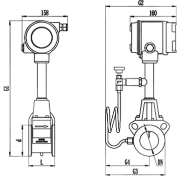
| Wafer type vortex |
 |
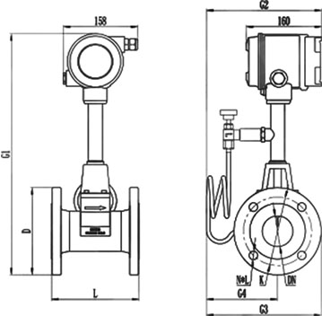
| Flange type vortex |
 |
 |
| Name |
Nominal Diameter |
Pressure class |
Total length |
Total height |
Total width |
Temperature pressure distan |
Flange outer diameter |
Housing outer diameter |
Bolt hole center distance |
Quantity and aperture |
| |
|
|
|
|
|
ce |
|
|
|
|
| DN |
Mpa |
L |
G1 |
G2/G3 |
G4 |
D |
d |
K |
N*L |
Wafer
type
unit
(mm) |
25 |
4.0 |
90 |
430 |
235 |
145 |
----- |
Φ57 |
----- |
----- |
| 32 |
4.0 |
90 |
435 |
235 |
145 |
----- |
Φ65 |
----- |
----- |
| 40 |
4.0 |
90 |
440 |
235 |
145 |
----- |
Φ75 |
----- |
----- |
| 50 |
4.0 |
90 |
460 |
235 |
145 |
----- |
Φ87 |
----- |
----- |
| 65 |
1.6 |
90 |
475 |
240 |
150 |
----- |
Φ109 |
----- |
----- |
| 80 |
1.6 |
100 |
510 |
240 |
150 |
----- |
Φ120 |
----- |
----- |
| 100 |
1.6 |
100 |
530 |
250 |
160 |
----- |
Φ149 |
----- |
----- |
| 125 |
1.6 |
100 |
555 |
290 |
200 |
----- |
Φ175 |
----- |
----- |
| 150 |
1.6 |
100 |
585 |
330 |
230 |
----- |
Φ203 |
----- |
----- |
| 200 |
|
|
|
|
|
----- |
|
----- |
----- |
| 250 |
|
|
|
|
|
----- |
|
----- |
----- |
| 300 |
|
|
|
|
|
----- |
|
----- |
----- |
Flange
type
unit
(mm) |
25 |
4.0 |
170 |
460 |
235 |
145 |
Φ115 |
----- |
Φ85 |
4×Φ14 |
| 32 |
4.0 |
174 |
475 |
235 |
145 |
Φ140 |
----- |
Φ100 |
4×Φ18 |
| 40 |
4.0 |
180 |
480 |
235 |
145 |
Φ150 |
----- |
Φ110 |
4×Φ18 |
| 50 |
4.0 |
186 |
500 |
235 |
145 |
Φ165 |
----- |
Φ125 |
4×Φ18 |
| 65 |
1.6 |
186 |
515 |
240 |
150 |
Φ185 |
----- |
Φ145 |
4×Φ18 |
| 80 |
1.6 |
200 |
550 |
250 |
150 |
Φ200 |
----- |
Φ160 |
8×Φ18 |
| 100 |
1.6 |
204 |
565 |
270 |
160 |
Φ220 |
----- |
Φ180 |
8×Φ18 |
| 125 |
|
|
|
|
|
|
----- |
|
|
| 150 |
|
|
|
|
|
|
----- |
|
|
| 200 |
|
|
|
|
|
|
----- |
|
|
| 250 |
|
|
|
|
|
|
----- |
|
|
| 300 |
|
|
|
|
|
|
----- |
|
|
 |
| Code |
Nominal Diameter |
Flow Range |
Remarks |
| Liquid(m3/h) |
Gas(m3/h) |
Focvor-25
Focvor-32
Focvor-40
Focvor-50
Focvor-65
Focvor-80
Focvor-100
Focvor-125
Focvor-150
Focvor-200
Focvor-250
Focvor-300 |
DN25
DN32
DN40
DN50
DN65
DN80
DN100
DN125
DN150
DN200
DN250
DN300 |
1-12
1.5-23
2.4-32
4-50
6.3-84
10-130
20-200
31-310
45-450
80-800
150-1500
200-2000 |
8-80
15-150
23-230
35-350
60-600
90-900
140-1400
220-2200
300-3000
550-5500
880-8800
1300-13000 |
|
| |
Code |
Function |
N
Y |
No Temperature & Pressure compensation
Temperature & Pressure compensation provided |
| |
Code |
Output signal |
F1
F2
F3
F4 |
4~20mA Output(two wires)
4~20mA Output(three wires)
RS485 communication interface
Frequency Output |
| |
Code |
Measured medium |
J1
J2
J3 |
Liquid
Gas
Steam |
| |
Code |
Connection mode |
L1
L2 |
Flange Wafer Type
Flange Connection Type |
| |
Code |
Function |
E1
E2
T1
T2
T3
P1
P2
P3
D1
D2
B1 |
class 1.0
class 1.5
Normal temperature
Moderate temperature
High Temperature
1.6Mpa
2.5Mpa
4.0Mpa
Internal 3.6V power supply
DC24 power supply
304 Stainless steel |
| |
| Focvor-25 |
Y |
F1 |
J1 |
L1 |
E1T1P1D2B1 |
Product • Installation Diagram
Many installation matters need attention |2017 Overall Upgrade | HUAHAI Instrument will display for you
The diagram shows the requirements of vortex flowmeter for the length of the upstream and downstream straight pipe
(a)One 90 °elbow;(b) Concentric flaring; (c) Concentric contractive full-open valve;
(d) Two 90°elbows on different planes; (e) Half-open valve of regulating valve; (f) Two 90° elbows on one plane |
Installation Precautions
| Vortex flowmeter must ensure that the upstream and downstream straight pipe sections have the necessary length, as shown. In various data, the data are different, the reason may be that the vortex generation body has not been standardized, and the influence of difference in shape and size remains to be verified; It is not enough to study the necessary straight pipe section length for all kinds of bluff body, that is, it is not yet mature.Compared with the throttling type differential pressure flowmeter, this work is still in the initial stage. |
Enterprise honorary qualification
|
Picture of electromagnetic flow meter equipment
|
Picture of client using HUAHAI instruments
|