RSS

Blog posts of '2018' 'September'

Precautions in the use of magnetic flapper level indicator

The magnetic flapper level indicator, also called the magnetic float level gauge,is a kind of field level gauge that the magnetic float picks up reed switch of the corresponding position in the sensor while the rise and fall of liquid level,so that the total resistance (or voltage) in the sensor changes correspondingly, and then converts the change of resistance (or voltage) into the standard current output of 4-20mA DC through the transmitter.

When purchasing a magnetic flapper level indicator, you should pay attention to:

1. The parameters of the product must be known in advance. For example, the corrosive medium needs anti-corrosion material, and the anti-corrosion grade varies according to the corrosive grade of the medium.

2. The special condition of the equipment also determines the installation method of the magnetic flapper level indicator, because some occasions are not suitable or not applicable at all.

Therefore, when purchasing, the user should first make clear the operating situation of their equipment and what the medium is, and then consider how to choose the magnetic flapper level indicator from the following aspects:

(1) The magnetic flapper level indicator should be tightly attached to the main leading pipe of the liquid level gauge and fixed with a stainless steel hoop;

(2)The induction surface should be oriented and tightly attached to the main leading pipe.

(3) The zero position of the magnetic flapper level indicator shall be on the same horizontal line as the zero position indication of the liquid level gauge;

(4) The connection between the magnetic flapper level indicator and the display instrument or the industrial computer is preferably laid by a protective tube alone or with a shielded two-core cable;

After the inlet hole of the junction box is laid, the sealing is required to be good, so as to prevent the intrusion of rainwater and moisture, so that the remote transmission instrument can not work normally. The junction box should be covered in time after the repair or debugging is completed.

Finally, users also need to remove impurities from the main leading pipe from time to time depending on the medium.

Characteristics of single loop digital display controller

With the continuous development of digital technology and microcomputer technology, digital display meters and new display and recording instruments with single-chip microcomputer as the core are more and more widely used in the field of industrial automation and industrial control. The digital display meter, like the pointer meter, matches with various sensors and transmitters to measure electric power, pressure, level, liquid level, flow rate and temperature, and directly displays the measured results in digital form.

Classification of digital display meters:

According to the signal form: ammeter, voltmeter, frequency meter...

According to the number of measurements:single point meter, multi-point meter

According to function: simple display, display alarm meter, display transmission meter, display communication meter, display record meter, multi-function meter, etc.

Characteristics of single loop digital display controller

Simple measurement and display controller adopts modular structure scheme, simple structure, easy operation, cost-effective,and high cost performance. It is suitable for plastics, food, packaging machinery and other industries.

★Single channel input, dual screen LED digital display.

★ With 33 kinds of signal input functions, the input signal type can be arbitrarily selected,and the measurement accuracy is 0.3%.

★The resolution of thermal resistance\thermocouple signal can be switched: 1°C or 0.1°C.

★ With upper and lower limit alarm function, with LED alarm lamp indication.

★ The voltage and current transmission output signals are optional.

★ Support RS485 serial interface, using standard MODBUS RTU communication protocol.

★ With DC24V feed output,power distribution for field transmitter.

★ Photoelectric isolation technology is used each other among input, output, power supply, and communication.

★It has many outline dimensions and styles for users to choose.

★ After the parameter is set, the password is locked, and the parameter setting is permanently saved after power off.

Characteristics of liquid level transmitter

The liquid level transmitter has throw-in type level transmitter (rod type, cable type),flange type level transmitter (single flange, double flange) and magnetic flapper level transmitter and floating ball level transmitter , etc.

The characteristics of Huahai series throw-in type level transmitter are flexible installation, convenient use, simple calibration,field display,signal isolation and amplification,cutoff frequency interference design,strong anti-interference ability,anti-condensation,lightning protection,anti-corrosion,anti-clogging design,etc.The probe diameter can be selected from 19mm to 42mm,with wiring reverse and overvoltage protection,current limiting protection, and ultra-wide price range for easy selection.

Working principle: the throw-in type level transmitter is a static pressure level gauge that uses the pressure principle to measure the liquid level.Generally the length of the throw-in type cable is equal to the length from the lowest point of the measured liquid level to the highest liquid level plus the distance from the mounting plane to the highest point of the liquid level.Using static pressure measurement principle:

When the throw-in type level transmitter is put into a certain depth of the measured liquid,the pressure on the liquid-facing surface of the sensor is: P =ρ.g.H + Po

P:pressure on the liquid-facing surface of the liquid level gauge

ρ:the density of the measured liquid

g:local gravity acceleration

Po:atmospheric pressure on the liquid surface

H:the depth of the throw-in type level transmitter into the liquid.

At the same time, the pressure of the liquid is introduced into the positive pressure cavity of the sensor through the gas-conducting stainless steel, and then the atmospheric pressure Po on the liquid surface is connected with the negative pressure cavity of the sensor to offset the Po on the back of the sensor, so that the pressure measured by the sensor is:ρ.g.H,obviously, by measuring the pressure P, the liquid level depth can be obtained.

Application areas of the throw-in type level transmitter: low liquid level monitoring of open liquid tanks,depth or level measurement of wells or open waters,groundwater level measurement,level measurement and control in sewage treatment, water supply, chemical and pharmaceutical industries,constant pressure water supply systems and other industries.Over temperature compensation and linear correction. Converted to 4-20mADC standard current signal output.The sensor part of the throw-in type level transmitter can be directly put into the liquid,and the transmitter part can be fixed by flange or bracket,which is very convenient for installation and use.

Characteristics of throw-in type level transmitter

1. Long service life

 The diaphragm of the liquid level transmitter adopts a high-tech laser modulation circuit, and the sensor housing is made of stainless steel.

2. Easy installation

  It is only necessary to put the probe of the throw-in type level transmitter into the liquid,and lead the signal line to connect the secondary instrument for liquid level measurement.

3. Good temperature stability

  The throw-in type level transmitter itself realizes temperature compensation in 0-70 °C, and a temperature compensation circuit is added in the signal conversion circuit to eliminate the influence of temperature drift of the circuit on the accuracy, ,thereby improving accuracy.

Precautions for pressure transmitter

1.Do not apply voltage higher than 36V to the transmitter, resulting in damage to the transmitter;

2.Do not touch the diaphragm with hard objects, resulting in damage to the isolation diaphragm;

3.The measured medium is not allowed to freeze, otherwise the isolation diaphragm of sensor elements will be damaged,resulting in damage to the transmitter.If necessary, the transmitter should be temperature-protected to prevent freezing.

4.When measuring steam or other high-temperature media,its temperature should not exceed the limit temperature when the transmitter is used.If the temperature is higher than the limit temperature when the transmitter is used,the radiator must be used;

5.When measuring steam or other high-temperature media,the radiating pipe shall be used to connect the transmitter with the pipeline,and the pressure on the pipeline should be transmitted to the transformer.When the measured medium is water vapor, a proper amount of water should be injected into the radiating pipe to prevent the superheated steam from directly contacting the transmitter and damaging the sensor;

6: During the process of pressure transmission,the following points should be noted:

1)Do not leak air at the connection between the transmitter and the radiating pipe;

2) Before starting to use,if the valve is closed, the valve should be opened very carefully and slowly, so as to prevent the measured medium from directly impacting the sensor diaphragm and damaging the sensor diaphragm;

3) The pipeline must be kept unimpeded, the sediment in the pipeline will pop up and damage the sensor diaphragm;

How is the error in the use of electromagnetic flow meters generated?

Electromagnetic flow meters have many advantages,but if the selection, installation and use are improper,they will cause an increase in error,unstable indication, and even damage to the body.

(1) The liquid in the pipe is not fully filled. Due to insufficient back pressure or poor installation position of the flow sensor, the measured liquid in the pipe is not fully filled, and the fault phenomenon is different due to the degree of not fully filled and flow condition.If a small amount of gas shows stratified flow or wave flow in the pipeline, the fault phenomenon shows that the error increases, that is, the flow measurement value is not consistent the actual value.If the flow is bubble flow or plug flow,the fault phenomenon will not only show that the measured value is not consistent with the actual value, but also appear output sloshing because of the gas phase covering the electrode surface instantaneously. If the gas phase part of the flow cross-sectional area of the stratified flow in the horizontal pipeline increases, that is, the degree of liquid not fully filled increases,and the output sloshing will also occur.If the degree of liquid not fully filled is more serious,so that the liquid level below the electrode, the output over-fullness phenomenon will occur.

(2) The liquid contains solid phase, and the liquid contains solids such as powder, particles or fibers,which may cause faults, such as: ① slurry noise; ②electrode surface contamination; ③conductive deposition layer or insulating deposition layer covers the electrode or lining;④the lining is worn or covered by sediment,and the flow cross-sectional area is reduced.

(3) Liquids that may crystallize, electromagnetic flow meters should be carefully used with some easily crystallized chemical materials. They can be measured normally under normal temperature conditions,because the pipe for conveying the fluid has good heat insulation,it will not crystallize during the heat preservation work,but the measuring tube of the electromagnetic flow sensor is difficult to carry out the heat insulation,therefore, when the fluid flows through the measuring tube,it is easy to cause a layer of solid on the inner wall due to the temperature drop.Since the flow meter measurement using other principles also has crystallization problems, therefore, in the absence of other better methods, a "ring" electromagnetic flow sensor with a very short measuring tube length can be selected, and the upstream pipeline of the flow meter can be strengthened with heat insulation.In the connection method of pipeline,it should be considered that the flow sensor is easy to be disassembled and installed,and it can be easily disassembled and maintained once it is crystallized.

(4) Problems caused by improper selection of electrodes and grounding ring materials.The parts of electromagnetic flow meter contacting with the medium are electrode and grounding ring,and the electromagnetic flow meter causing fault due to mismatch between material and measured medium,in addition to the problem of corrosion resistance,there are surface effects of electrodes. Surface effects should include:①chemical reactions (passive film formed on the surface etc.);②electrochemical and polarization phenomena (generating potential); ③catalyst action(aerial fog formed on the electrode surface, etc.).Grounding rings also have these effects, but the impact is less.

(5) The problem that the liquid conductivity exceeds the allowable range,and if the liquid conductivity is close to the lower limit, there may be a sloshing phenomenon.Because the lower limit specified by the manufacturer's instrument specification is the lowest value that can be measured under various conditions of better use,and the actual conditions are not all ideal, so low-degree distilled water or deionized water is encountered many times,and its conductivity is close to the lower limit value 5 specified by the electromagnetic flow meter specification, and output sloshing occurs when using.The lower limit of the conductivity that can be measured stably is generally considered 1~2 orders of magnitude higher.

 The conductivity of the liquid can be found in the relevant manual.If the data is not available, the sample can be measured with a conductivity meter.However, there are cases where sampling from the pipeline to laboratory determination is considered to be available and the actual electromagnetic flow meter does not work.This is because the liquid at the time of measuring conductivity is different from the liquid in the pipeline. For example, the liquid has absorbed CO2 or NO in the atmosphere to form carbonic acid or nitric acid, and the electrical conductivity is increased.

Maintenance knowledge of pressure transmitter

.Advantages of Huahai pressure transmitter

Smart pressure transmitter has small volume, light weight, high accuracy, good reliability and good overload performance; has adjustable damping device,which can be used for the measurement of pulsating fluid;The transmitter adopts 4~20mA DC standard current signal output, two-wire system,with load, strong anti-interference ability.


.Technical advantages of Huahai pressure transmitter

1. Small volume and light weight of pressure transmitter. Because it has few parts, simple mechanism, and the transformation of differential pressure, displacement and capacitance signal is connected together, the volume is greatly compressed and the weight is reduced.

2. High accuracy. Because there is no mechanical transmission and friction, and the capacitance value changes relatively greatly, so the precision is easy to make high.

3. Reliability is good. Due to the small number of movable parts, the measuring part is a solid structure of fully enclosed welding, the electronic components undergo strict aging screening, and a special connector body is adopted, thereby greatly improving the reliability of the transmitter.

4. The range can be adjusted in a wide range, and it has a positive and negative shift structure.The adjustable range of the range is greater than 6:1, and the external connection of the range zero is adjustable.

5. The overload performance is good. The inside of the sensor adopts a concave arc surface overload protection structure with simple structure and reliable performance.

6. With adjustable damping device, it can be used for the measurement of pulsating fluid.

7. The transmitter is used in a dedicated circuit for flameproof and intrinsically safe type. The maximum output of this circuit is less than 30mA.

8. The transmitter can be attached with 100% pointer, LCD liquid crystal, LED digital tube display, and the field reading is very convenient.

9. The transmitter adopts 4~20mA DC standard current signal output, two-wire system, with load, strong anti-interference ability.

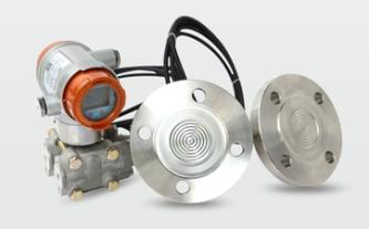
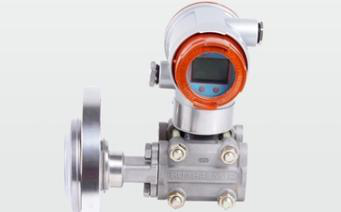
                   Single flange transmitter           Smart pressure transmitter      Pressure transmitter with remote device


.Maintenance knowledge of pressure transmitter

1. Prevent dregs from depositing in the pipe.

2. The pressure guiding tube should be installed in a place with small temperature fluctuations.

3. First,pressure transmitters should be prevented from contacting corrosive or overheated media.

4. When measuring the liquid pressure, the pressure tappings should be located on the side of the process pipeline to avoid deposition of slag.

5. When measuring the liquid pressure, the installation position of the pressure transmitter should avoid the impact of the liquid , so as to avoid the overpressure damage of the pressure transmitter.

6. When wiring, pass the cable through the waterproof joint and tighten the sealing nut to prevent rainwater from leaking into the transmitter housing through the cable.

7. When the pressure transmitter measures the gas pressure,the pressure tappings should be located at the top of the process pipeline,  and the pressure transmitter should also be installed in the upper part of the process pipeline so that the accumulated liquid can be easily injected into the process pipeline.

8. When freezing occurs in winter, if the pressure transmitter is installed outdoors,anti-freezing measures must be taken on the instrument to avoid the liquid in the pressure tappings from volume expansion due to freezing, resulting in the damage of the sensor.

Thermal gas mass flow meter

Thermal gas mass flow meter adopts the traditional differential pressure flow meter principle to ensure the durability,practicability and long service life of the product,and has the advantages of high measurement accuracy and good stability.Flow measurement instrument for various gas flow measurement,the complete system of thermal gas mass flow meter consists of:flow sensor (bend sensor), intelligent liquid crystal host,temperature and pressure compensation components and instrument valve assembly.It is suitable for the measurement of round pipe,square pipe,pure gas or dirty gas.Typical applications:measurement of gas mediums such as large and small caliber blast furnace gas,coke oven gas,producer gas,boiler primary air,secondary air,tertiary air, compressed air,oxygen,nitrogen,carbon dioxide,chlorine.

Thermal gas mass flow meter consists of a ceramic semiconductor sensor, temperature sensor and control device.The ceramic semiconductor sensor has a characteristic of dynamic change of its own impedance along with the change of ambient temperature. If the velocity of the fluid changes, the surrounding temperature changes, and the impedance of the ceramic semiconductor sensor itself changes.This characteristic is used to measure the velocity and flow of fluid.In order to compensate the change of the fluid with temperature, thermal gas mass flow meter is equipped with a temperature compensation sensor.The reflection of the non-linear characteristics of the fluid by the ceramic semiconductor sensor needs to be processed by the embedded microprocessor. The instrument is based on the Coriolis Force principle for direct and precise measurement of fluid mass flow without any conversion or correction of pressure, temperature, viscosity, density, etc.The measured flow rate is directly displayed on the electronic unit panel by mass flow unit (kg/h, t/h or g/s), and the remote standard signal 0-10KHz,4-20mA and 1-5V are output on the back terminal of the electronic unit.The flow meter has no movable parts,wide range ratio (greater than 5:1), high accuracy (±0.2%), high pressure resistance, wide temperature range, and can be used to measure the flow of high viscosity (within 10000 CP) and non-Newtonian fluids.

The above characteristics make the instrument widely used in oil fields, refineries, chemicals, building materials, food, medicine, leather, paper making, coatings, dyes, nuclear energy, metallurgy, aerospace and other sectors. The material of the flow sensor is made of 316L stainless steel with good corrosion resistance.

Characteristics

1. The circuit adopts surface mounting technology, with compact structure and high reliability.

2. Adopting the high and new technology of micro-power consumption,both internal and external power supply can work,the power consumption of the whole machine is low;

3.Adopting high-performance microprocessor and modern filtering technology,with powerful software functions and superior performance;

4. No mechanical movable parts,good stability, not easy to corrode, no mechanical maintenance;

5. Low requirements for front and rear straight pipe segments,front≥ 3DN,rear≥ 1DN;

6. High contrast liquid crystal display can display accumulative flow and instantaneous flow,easy to read,clear and intuitive;

7. The instrument has the function of password setting to prevent illegal**** setting;

8. The instrument has the function of data preservation in case of power failure;

9. Display the flow value locally,and remote output the pulse signal and (4-20) mA standard analog signal,which is convenient for connection with the secondary instrument.

Selection of pressure / differential pressure transmitter

Selection principle

When selecting the model, the corrosion of the measured fluid medium to the metal of the diaphragm capsule should be considered,the material of the diaphragm capsule of the transmitter is ordinary stainless steel, 304 stainless steel, 316/316L stainless steel, tantalum and so on.If the measured medium is highly viscous,easily crystallized, and highly corrosive,an isolated type transmitter must be selected.

When selecting the model, the temperature of the measured medium should be considered. If the temperature is high enough to reach 200 ~400℃, the high temperature type should be selected.Otherwise, the silicone oil will produce vaporization expansion, which makes the measurement inaccurate.

The isolated type pressure transmitter is preferably threaded connection, which saves money and facilitates installation.

According to the design specifications, in the selection of engineering design, whether pneumatic or electric transmitters are used should be comprehensively considered and analyzed according to the specific conditions of the device because of their speciality.

In general, the following conditions are preferred for the selection of pneumatic transmitters:

※ The distance from the transmitter to the display adjustment unit is short, usually not more than 150 meters;

※ The process materials are flammable and explosive medium and the relative humidity is very large;

※ Requires occasions where the instrument investment is less and the response speed is not fast;

※ Generally, small and medium-sized enterprises require easy maintenance and economic and reliable;

※ In large installations based on electric meters, some on-site control loops are not require centralized operation of the central control room.

The following conditions are preferred for the selection of electric transmitters:

※ The distance between the transmitter and the display adjustment unit is more than 150 meters;

※ Large enterprises require central control with highly centralized management;

※ Set up the objects controlled and managed by DCS computer;

※ Requires occasions where has fast response, information processing and complex computing;

In practice, in modern production installations, they are mixed and selected according to their respective characteristics.

Selection of pressure transmitter

From a physical point of view,the pressure on any object includes both atmospheric pressure and the pressure of the measured medium (generally referred to as gauge pressure). The sum of the pressures of the two parts acting on the measured object is called the absolute pressure.

P absolute = P gauge + atmospheric pressure

The instrument for measuring absolute pressure is called the absolute pressure gauge.For ordinary industrial pressure gauges, the gauge pressure value is measured, that is, the pressure difference between absolute pressure and atmospheric pressure.When the absolute pressure is greater than the atmospheric pressure value, the measured gauge pressure value is positive value, which is called positive gauge pressure; when the absolute pressure is less than the atmospheric pressure value, the measured gauge pressure value is negative value, which is called negative gauge pressure,that is, vacuum degree.The instrument for measuring the vacuum degree is called the vacuum gauge.

(1) In order to ensure the accuracy of pressure measurement, the minimum pressure measurement value should be higher than 1/3 of the measurement range of the pressure gauge;

(2) For occasions requiring remote distance measurement or high measurement accuracy, pressure sensors or pressure transmitters should be selected;

(3) When the measurement accuracy requirement is not high, the resistance type or inductance type, Hall effect type remote pressure transmitter can be selected.

(4) The pneumatic base type pressure indicating regulator is suitable for local pressure indication and adjustment;

(5) Pressure transmitter and pressure switch should be reasonably selected according to the explosion-proof requirements of the installation site. 

Selection of differential pressure transmitter

The differential pressure transmitter is selected according to the following points:

(1)Measuring range, accuracy and measurement function;

(2) The environment faced by the measuring instrument, such as the industrial environment of petrochemical industry, which has the existence of thermal (toxic) and explosive dangerous atmosphere and higher environmental temperature.

(3) Physicochemical properties and state of the measured medium, such as strong acid, strong alkali, viscous, easy solidification, crystallization and vaporization, etc.

(4) Changes in operating conditions, such as changes in medium temperature, pressure, and concentration. Sometimes changes in concentration and density of gas phase and liquid phase should be considered from the beginning to the normal production of the parameters.

(5) The structure, shape, size of the vessel ,equipment accessories in the vessel and all kinds of inlet and outlet pipes of the measured object shall be considered, such as towers, solution tanks, reactors, boiler steam drums, vertical tanks, spherical tanks, etc.;

(6) Other requirements, such as environmental protection and sanitation;

(7) There must be a unified consideration in the selection of engineering instruments, and it is required to reduce specifications and varieties as much as possible and reduce spare parts,in order to facilitate management;

(8) Actual process conditions

In summary, the selection of the transmitter is feasible in technology,reasonable in economy,and convenient in management.

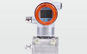
Pressure/differential pressure transmitter

Among all kinds of instruments, the transmitter is the most widely used and universal,and the transmitters are generally divided into pressure transmitters and differential pressure transmitters.Transmitters are commonly used to measure pressure, differential pressure, vacuum, level, flow and density. The transmitter has two-wire system and four-wire system,two-wire system transmitters more;There are intelligent and non-intelligent, intelligent transmitters gradually more;  There are pneumatic and electric, electric transmitters in the majority;In addition, according to the application,there are intrinsic safety type (intrinsic safety type) and explosion-proof type; according to the application under working conditions,the main types of transmitters are as follows:

※ Low (micro) pressure / low (micro) differential pressure transmitter;

※ Medium pressure / medium differential pressure transmitter;

※ High pressure / high differential pressure transmitter;

※ Absolute pressure/vacuum/negative pressure differential pressure transmitter;

※ High temperature / pressure, differential pressure transmitter;

※ Corrosion resistant / pressure, differential pressure transmitter;

※ Easily crystallized / pressure, differential pressure transmitter.

Transmitter selection is usually based on installation conditions, environmental conditions, instrument performance, economy, and media.In practical applications,it can be divided into direct measurement and indirect measurement;which are used for process measurement, process control and device interlocking.Common transmitters include ordinary pressure transmitter, differential pressure transmitter, single flange transmitter, double flange transmitter,insertion type flange transmitter, etc.

Pressure transmitters and differential pressure transmitters measure pressures and differential pressures (the difference between the two pressures) by name alone,but there are many quantities that can be indirectly measured.For example, pressure transmitter can measure the liquid level in the device besides measuring the pressure.When measuring the liquid level in an atmospheric pressure vessel, a pressure transmitter is required. When measuring the liquid level of the pressurized vessel,two pressure/differential pressure transmitters can be considered, that is, one lower limit of measurement, one upper limit of measurement, and their output signals are subtracted, and the liquid level can be measured.In this case, differential pressure transmitters are generally used. It can also be used to measure the density of a medium if the liquid level and pressure in the vessel are constant.The measurement range of the pressure transmitter can be made very wide, starting from absolute pressure 0 to more than 100 MPa (general condition).

In addition to measuring the differential pressure of the two measured pressures, the differential pressure transmitter can also measure the flow of the medium fluids with various throttling elements, and can directly measure the liquid level of the pressurized vessel and the liquid level of the atmospheric pressure vessel and pressure and negative pressure.

The structure of the pressure/differential pressure transmitter is divided into a common type and an isolated type.The measuring diaphragm capsule of the ordinary pressure/differential pressure transmitter is one, which directly senses the pressure or differential pressure of the measured medium; The measuring diaphragm capsule of isolated type receives a pressure of a stabilizing liquid (generally silicone oil) which is sealed between the two diaphragms and the diaphragm directly receiving the measured pressure is an outer diaphragm. The diaphragm of the original common type diaphragm capsule is an inner diaphragm.When the pressure signal is received on the outer diaphragm, the pressure of the outer diaphragm is transmitted to the ordinary diaphragm capsule by the transmission of the silicone oil, so that the pressure felt by the outer diaphragm can be measured.

About instrument calibration

In classic instrument management, the term "check" has been used.Now it is called calibration in measurement  management.Calibration is the whole job of determining the indication error(including determining other metering performance if necessary) of a measuring instrument.

I. Differences and similarities between calibration and verification

Calibration and verification are two different concepts, but there is a close relationship between the two. Calibration is compared a measuring instrument (referred to as a standard instrument) with a higher accuracy than the calibrated measuring instrument with the calibrated measuring instrument to determine the indication error of the calibrated measuring instrument,and sometimes also including some measuring performance,but the calibrated measuring instruments only need to determine the indication error.If the calibration is the verification content of the indication error in the verification work,it can be said that it is part of the verification work,but the calibration cannot be regarded as the verification.Moreover, the calibration requirements are not as strict as the verification, and the calibration can be performed at the production site, and the verification must be carried out in the verification room.

Some people understand calibration as the process of adjusting the measuring instrument to the specified error range,which is not accurate enough.Although it can be adjusted during the calibration process, the adjustment is not equal to the calibration.

II. Basic requirements for calibration

The basic requirements for calibration should be as follows:

(1) Environmental conditions,if the calibration is carried out in the verification (calibration) room, the environmental conditions should meet the temperature, humidity and other regulations required by the laboratory. If the calibration is carried out on site, the environmental conditions shall be subject to the conditions that instrument can be used on-site.

(2) The instrument, as a standard instrument for calibration,the error limit should be 1/3~1/10 of the error limit of the calibrated instrument.

(3) Personnel, although the calibration is different from the verification, the personnel who perform the calibration should also be effectively assessed and obtain the corresponding certificate.Only the certificate holder can issue the calibration certificate and calibration report, and only such certificate and report can be considered effective.